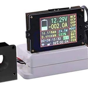
Wireless voltage / current / temperature meter with LCD display VAC8010F 500V 100A
€ 88.00 + € 5.00 DELIVERY


Description
Wireless voltage / current / temperature meter with LCD display VAC8010F 500V 100A NB: The images are for illustrative purposes only, some colors or finishes may differ Technical specifications Self-powered input voltage range 6 ~ 500V External power supply Volt input 0 ~ 120V Current 0 ~ 100A External power supply voltage 6-60V Display method 2.4 inch color LCD display Voltage measurement range 0 ~ 500V Current measurement range 0 ~ 100A Capacity measurement range 0.001AH ~ 65000.00AH Energy measurement range 0.000 KWH ~ 9999 KWH Time measurement interval 0 ~ 100 hours Power value measurement range 999KW Temperature measurement range 1 ~ 100 ℃ Voltage accuracy ± 1 % + 2 Current accuracy ± 2 % + 5 Temperature accuracy ± 1.5 ℃ Measurement rate 5 times / sec Type of protection and adjustment range OVP (over voltage protection) 0.01V ~ 500V LVP (undervoltage protection) 0.01 ~ 500V OCP (Charge Overcurrent Protection) 0-500A NCP (discharge overcurrent protection) 0-500A Display fields 1 Bar graph of remaining battery capacity 2 Cumulative number AH remaining 3 Cumulative energy 4 The time it takes to fully charge or discharge the battery (calculated based on charge and discharge current and capacity) 5 Indication of wireless communication signal 6 Key lock indication 7 Real-time measurement of temperature values 8 Cumulative value of the single execution time 9 Directory for displaying the output status A Percentage of the remaining battery capacity B Power value C Function option directory D Measured voltage value E Current measured value Measurement board interface description (right side image below) 1 Discharge relay control interface 2 Control interface of the charging relay 3 USB 2.0 interface (can supply power to the scoreboard) 4 Voltage measurement interface 5 External power supply interface 6 Interface for selecting external power supply and self power supply 7 Relay switch button External power supply wiring diagram Note: If the voltage range of the tested battery (power supply) does not work (6-80V), you can use the wiring mode of the external power supply. First, adjust the power supply selection interface jumper cap to "3W" and the external power supply. Connect the positive and negative poles to “+ Vext-”, pay attention to “+” to the positive pole of the external power supply and “-” to the negative pole of the external power supply; then connect the positive and negative poles of the battery (power supply) to the “+ Bat” voltage measurement socket. - ", pay attention to" + "to the positive pole of the battery (power supply)," - "to the negative pole of the battery (power supply). Do not connect the positive and negative poles of the battery (power supply) to the positive pole of the load. Connect the positive pole of the battery (power supply) to the positive pole of the load. The negative pole of the battery (power supply) is connected to the negative pole of the load through the Hall sensor when it flows through the Hall sensor. When the current direction is the same as the Hall sensor turn-on arrow direction, the measured current will show a positive value, otherwise the measured current will show a negative value. Charging relay wiring instructions Note: The working power of the relay is provided by an external power supply. If the relay is connected, an external power supply with the same working voltage as the relay should be provided. Connect the relay control port to the charge controller interface. If you want to check the positive pole of the charge, run the positive line through the relay. If you want to check the negative pole of the charge, connect the negative line to the relay. When the relay is connected, the "IN" lamp is used. It will turn on and off as a reminder when disconnected. Instructions for wiring the drain relay Note: The working power of the relay is provided by an external power supply. If the relay is connected, an external power supply with the same working voltage as the relay should be provided. Connect the relay control port to the discharge controller interface. If you want to check the positive pole of the discharge, pass the positive line through the relay. If you want to check the negative pole of the discharge, connect the negative line to the relay. When the relay is connected, the "OUT" light turns on and off as a reminder when disconnected.
Item Details
9818795
252
Consumer Electronics
11/09/2024
New